


Introduction
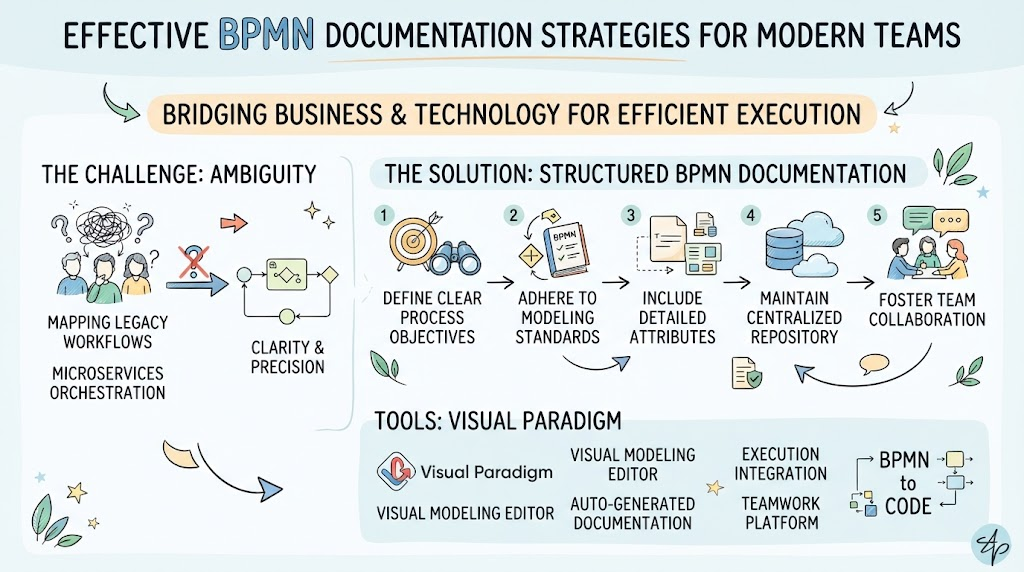
In the landscape of modern software development and business analysis, ambiguity is the enemy of efficiency. Whether you are mapping a legacy workflow for migration or designing a microservices orchestration layer, precise communication is paramount. Business Process Model and Notation (BPMN) serves as the universal language for this purpose, bridging the gap between business stakeholders and technical teams.
However, knowing the symbols is only half the battle. Creating process documentation that is both rigorous and readable requires adherence to best practices and the use of specialized tooling. This guide explores effective BPMN documentation strategies, specifically tailored for modern development teams, utilizing Visual Paradigm as the recommended platform for implementation. By leveraging standardized notation and powerful software tools, teams can transform abstract workflows into actionable, executable assets.
Core BPMN Concepts: Activities and Gateways
Before diving into best practices, it is essential to ground our understanding in the fundamental building blocks of BPMN as defined in standard modeling guides.
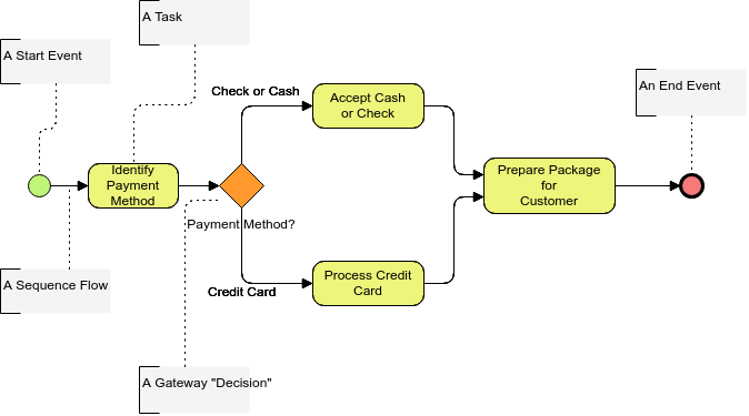
Activities and Sequence Flows
In a BPMN process diagram, all activities are depicted by rounded rectangles. These rectangles are connected by arrows, called sequence flows, which indicate the order of performance.
Parallel Gateways for Splitting and Merging
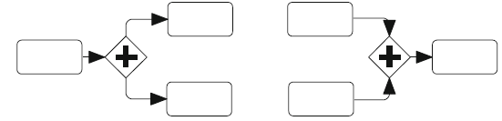
Where different courses of action are possible, branching points are required. These are called splitting gateways in BPMN and are depicted as diamonds. Synchronization constructs are also covered by merging gateways, which share the same diamond shape. In BPMN, a gateway can function as both a splitter and a merger depending on its context.
-
Splitting Parallel Gateway: Splits one path into several paths to be processed in parallel. There are no conditions for choosing paths; all outgoing sequence flows receive a token when the gateway fires.
-
Merging Parallel (Synchronizing) Gateway: Waits until there is at least one token of the same instance on every incoming sequence flow before producing a token on its outgoing sequence flow.
Best Practices for Clear and Effective Process Documentation
Creating a diagram is easy; creating a clear diagram requires discipline. Based on BPMN semantics and practical experience, adhere to these guidelines:
1. Respect the Bracketing Structure
Parallel splitting and merging gateways should generally follow a “bracketing structure.” Every path emerging from a splitting gateway should be synchronized at the respective merging gateway. While deviations are sometimes convenient, strict bracketing avoids design errors and simplifies the proving of process properties like deadlock freedom.
2. Distinguish Exclusive vs. Parallel Logic Clearly
Never rely solely on the reader’s intuition. Use the correct internal markers:
-
Exclusive Gateway (XOR): Used for decisions where only one path is taken (e.g., “Price > limit?”).
-
Parallel Gateway (+): Used when all paths are taken simultaneously.
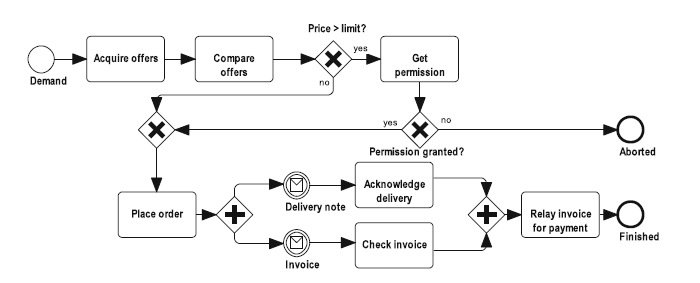
In the Order Process example below, note how the exclusive gateways handle conditional logic (“Permission granted?”), while the parallel gateway handles concurrent tasks (“Acknowledge delivery” and “Check invoice”). Also observe that exclusive splits do not always require a corresponding merge if a path terminates the process prematurely.
3. Maintain Consistent Granularity
A common pitfall is mixing high-level business phases with low-level system API calls in the same diagram. Keep abstraction levels consistent. If a task requires complex sub-processes, use collapsed sub-process markers rather than cluttering the main flow.
4. Label Gateways and Flows Explicitly
Unlabeled outgoing flows from exclusive gateways are a primary source of misinterpretation. Always label the condition on the sequence flow or the gateway itself. For parallel gateways, labels are typically unnecessary unless distinguishing specific resource allocations.
Usage Cases for Modern Development Teams
BPMN is no longer just for business analysts. Modern engineering teams leverage these diagrams for technical precision:
| Usage Case | Description | Benefit for Dev Teams |
|---|---|---|
| Microservices Orchestration | Modeling saga patterns, event-driven architectures, and service dependencies using parallel gateways and message flows. | Visualizes distributed transactions and identifies compensation logic requirements. |
| CI/CD Pipeline Design | Mapping build, test, and deployment stages as tasks; using parallel gateways for concurrent testing suites. | Identifies bottlenecks and ensures synchronization before production deployment. |
| API Workflow Specification | Defining the exact sequence of API calls, error handling (exclusive gateways), and retry logic. | Serves as a contract between frontend/backend teams and QA automation scripts. |
| Legacy System Migration | Documenting “As-Is” processes to identify hidden business rules before refactoring to “To-Be” cloud-native architectures. | Prevents loss of critical business logic during modernization. |
| Compliance & Audit Trails | Creating formalized documentation for SOC2, GDPR, or HIPAA compliance directly from engineering workflows. | Reduces audit preparation time by keeping docs synced with actual implementation. |
Why Visual Paradigm is the Recommended Tool
While generic drawing tools can create BPMN shapes, they lack semantic intelligence. Visual Paradigm is recommended for professional process documentation because it treats BPMN as a model, not just a picture.
Key Advantages:
-
Semantic Validation: Visual Paradigm enforces BPMN 2.0 standards. It prevents invalid connections (e.g., connecting two events directly without an activity) and warns about unbalanced gateways, ensuring your “bracketing structure” is mathematically sound.
-
Model-to-Code Integration: Unlike static image editors, Visual Paradigm supports round-trip engineering. You can generate code skeletons from your BPMN diagrams or reverse-engineer existing codebases into process models.
-
Collaborative Repository: The tool offers a centralized repository for version control, allowing distributed teams to manage “As-Is” and “To-Be” analyses collaboratively without file conflicts.
-
Rich Example Library: Access to vetted templates accelerates modeling. For instance, the Vendor Management System example below demonstrates a complete “to-be” purchasing process with proper gateway usage and connector styling, serving as an immediate reference for team standards.
BPMN Example – Business Process Diagram: Vendor Management System
This diagram illustrates a to-be purchasing process for creating new Vendors, showcasing multiple tasks, decision gateways, and connectors in a production-ready format.
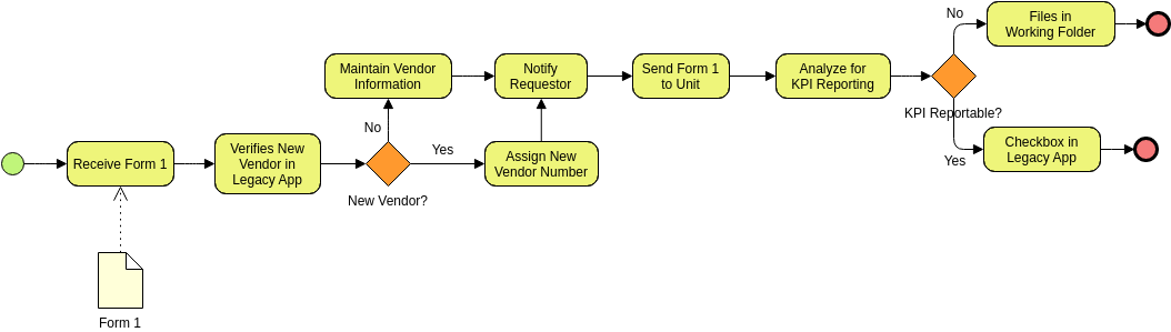
(Edit The above BPMN Example online)
Learning Resources
For teams adopting this tooling, Visual Paradigm provides integrated learning paths:
-
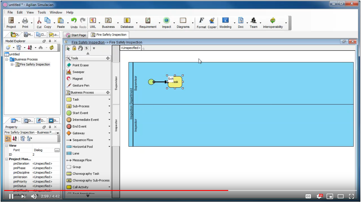
Video Tour: Take a Quick Tour of Visual Paradigm BPMN
-
Academic Rigor: Refer to A Rigorous Semantics for BPMN 2.0 Process Diagrams by Felix Kossak et al. for deep theoretical backing.
-
Practical Guides: Business Process Design with Powerful BPMN Software and Modeling As-Is and To-Be Analysis using BPMN.
Conclusion
Effective process documentation is a strategic asset that reduces technical debt, aligns cross-functional teams, and ensures regulatory compliance. By mastering core BPMN concepts—particularly the disciplined use of parallel and exclusive gateways—and adhering to best practices like bracketing structures and consistent granularity, organizations can achieve clarity in complexity.
Adopting Visual Paradigm elevates this practice from simple diagramming to professional process engineering. Its validation capabilities, integration features, and rich template library empower modern development teams to build systems that are not only well-documented but inherently well-designed. Start with the fundamentals, leverage the right tools, and let your process models drive successful digital transformation.
Related posts:
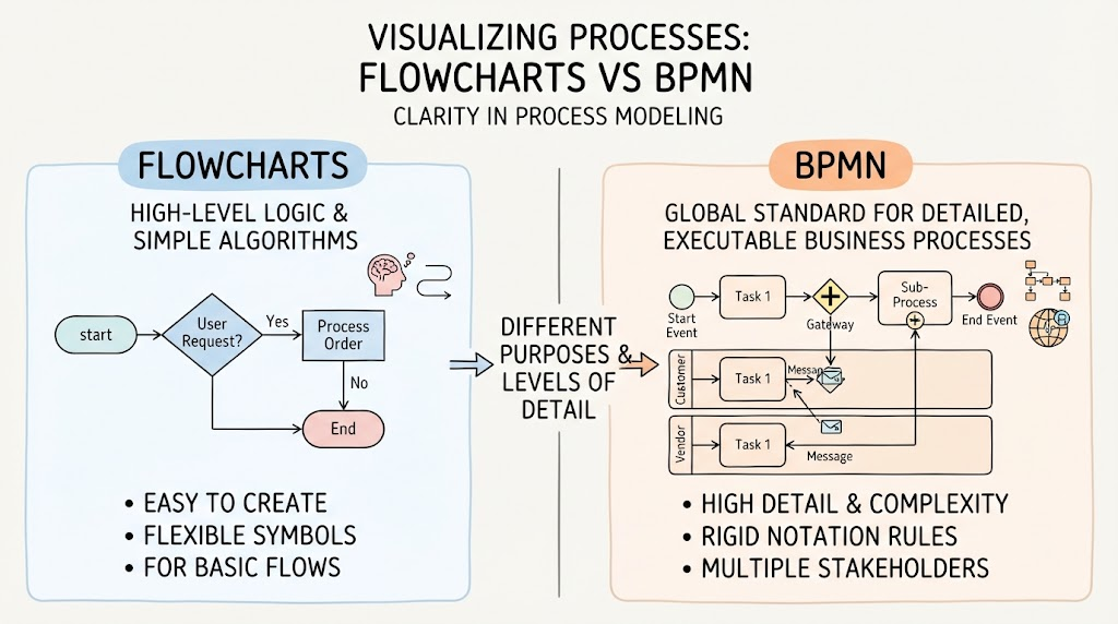 BPMN vs. Flowcharts: Understanding the Key Differences and When to Use Each
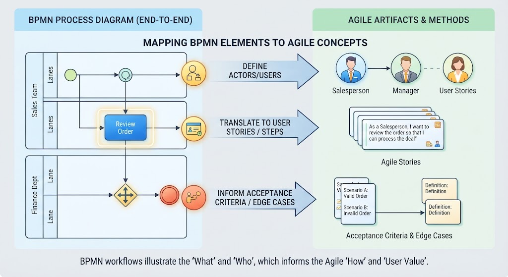 From Process to Product: Translating BPMN Diagrams into Agile User Stories
 Taming Spaghetti Diagrams: AI-Assisted Refactoring for Cleaner BPMN Architecture
Mastering BPMN Intermediate Events: A Practical Guide Using Visual Paradigm
Taming Spaghetti Diagrams: AI-Assisted Refactoring for Cleaner BPMN Architecture
Mastering BPMN Intermediate Events: A Practical Guide Using Visual Paradigm