Introduction
Business Process Model and Notation (BPMN) has become the global standard for visualizing business processes. Whether you’re a business analyst, process owner, or product manager, understanding how to effectively model workflows is essential for improving operational efficiency, identifying bottlenecks, and facilitating clear communication across teams.
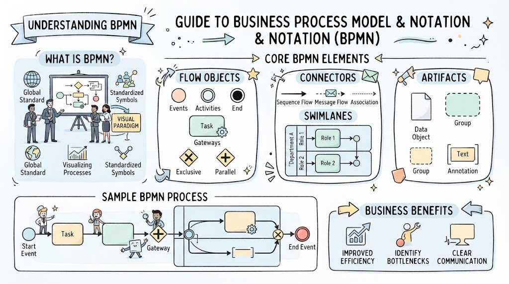
This guide provides a comprehensive overview of BPMN’s core elements—flow objects, connectors, artifacts, and swimlanes—and demonstrates how to apply them using Visual Paradigm, a powerful modeling tool that supports BPMN 2.0 standards. By the end of this article, you’ll have a solid foundation for creating clear, actionable process diagrams that drive real business value.
Key Concepts in BPMN
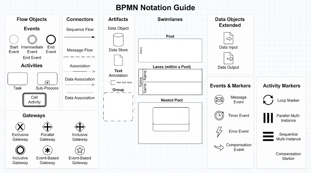
1. Flow Objects: The Heart of Your Process
Flow objects are the primary building blocks that define what happens in your process.
Events (Circles)
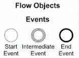
Events represent something that occurs during a process. They come in three types:
-
Start Events: Trigger the beginning of a process (e.g., “Customer submits order”)
-
Intermediate Events: Occur between start and end (e.g., “Payment confirmed,” “Approval received”)
-
End Events: Mark the completion of a process (e.g., “Order shipped,” “Invoice sent”)
Example: In an e-commerce order fulfillment process, a start event might be “Order Placed,” an intermediate event could be “Payment Verified,” and an end event would be “Package Delivered.”
Activities (Rounded Rectangles)
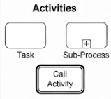
Activities represent work that needs to be performed. They can be:
-
Tasks: Atomic units of work that cannot be broken down further
-
Sub-processes: Compound activities that contain their own internal flow
Example: “Verify Customer Identity,” “Process Payment,” and “Generate Shipping Label” are all tasks within an order processing workflow.
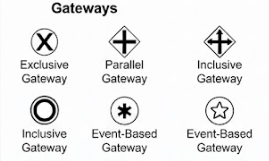
Gateways (Diamonds)
Gateways control the flow of the process by splitting or merging paths:
-
Exclusive Gateway (XOR): Only one path can be taken (e.g., “Is payment approved? Yes/No”)
-
Parallel Gateway (AND): Multiple paths execute simultaneously (e.g., “Notify warehouse” AND “Send confirmation email”)
-
Inclusive Gateway (OR): One or more paths may be taken based on conditions
Example: After receiving an order, an exclusive gateway might check inventory: if items are in stock, proceed to packing; if not, trigger a backorder process.
2. Connectors: Linking Your Process Together
Connectors establish the sequence and communication between flow objects.
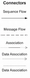
Sequence Flow (Solid Line with Solid Arrowhead)
Shows the order in which activities are performed within the same pool.
Example: “Receive Order” → “Validate Order” → “Process Payment” shows a clear sequential workflow.
Message Flow (Dashed Line with Open Circle and Arrowhead)
Illustrates communication between different pools (participants), such as between a customer and a company.
Example: A message flow from the “Customer” pool to the “Order Processing” pool might represent “Submit Order Request.”
Association (Dotted Line)
Links annotations or data objects to flow objects without affecting execution.
Example: Connecting a data object “Customer Profile” to the “Verify Identity” task shows what information is needed.
3. Artifacts: Adding Context Without Changing Flow
Artifacts provide supplementary information to enhance understanding.
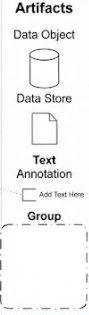
Data Object (Folded Paper Icon)
Represents input or output data associated with activities.
Example: An invoice document produced by the “Generate Invoice” task, or customer data consumed by the “Validate Account” activity.
Text Annotation (Bracketed Text Box)
Allows designers to add explanatory notes for clarity.
Example: A note attached to a gateway explaining: “Approval required for orders over $5,000.”
Group (Dashed-Dotted Rounded Box)
Visually categorizes related activities without affecting logic.
Example: Grouping all payment-related tasks under “Payment Processing” for better organization.
4. Swimlanes: Defining Responsibilities
Swimlanes clarify who does what in a process.
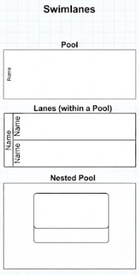
Pools
Represent independent participants or organizations. Each pool contains its own process flow.
Example: In a vendor procurement process, you might have separate pools for “Buying Company” and “Supplier.”
Lanes
Sub-divisions within a pool that assign activities to specific roles, departments, or systems.
Example: Within the “Buying Company” pool, lanes could include “Procurement Team,” “Finance Department,” and “IT System.”
Practical Example: Order Fulfillment Process
Let’s walk through a real-world example using all BPMN elements.
Scenario
An online retailer needs to model their order fulfillment process from customer purchase to delivery.
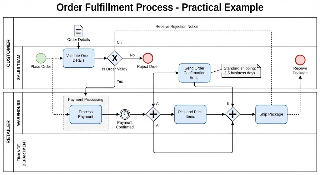
BPMN Diagram Structure
Pools:
-
Customer
-
Retailer
Lanes within Retailer Pool:
-
Sales Team
-
Warehouse
-
Finance Department
Process Flow:
-
Start Event (Customer Pool): “Place Order”
-
Message Flow: Order details sent to Retailer pool
-
Task (Sales Lane): “Validate Order Details”
-
Exclusive Gateway: “Is order valid?”
-
No → End Event: “Reject Order” with notification to customer
-
Yes → Continue
-
-
Task (Finance Lane): “Process Payment”
-
Intermediate Event: “Payment Confirmed”
-
Parallel Gateway: Split into two paths:
-
Path A: Task (Warehouse Lane): “Pick and Pack Items”
-
Path B: Task (Sales Lane): “Send Order Confirmation Email”
-
-
Task (Warehouse Lane): “Ship Package”
-
End Event (Customer Pool): “Receive Package”
Artifacts:
-
Data Object: “Order Details” linked to validation task
-
Text Annotation: “Standard shipping: 3-5 business days”
-
Group: “Payment Processing” encompassing finance tasks
Using Visual Paradigm for BPMN Modeling
Visual Paradigm is an enterprise-grade modeling tool that fully supports BPMN 2.0. Here’s how to leverage it effectively:
Getting Started
-
Create a New BPMN Diagram
-
Open Visual Paradigm
-
Select “New Diagram” → “Business Process Model”
-
Choose BPMN 2.0 as the notation standard
-
-
Add Pools and Lanes
-
Drag a “Pool” element from the palette
-
Right-click the pool to add lanes for different roles
-
Name each lane appropriately (e.g., “Customer Service,” “Engineering”)
-
-
Model Flow Objects
-
Use the toolbar to add events (circles), activities (rounded rectangles), and gateways (diamonds)
-
Double-click elements to add labels and configure properties
-
-
Connect Elements
-
Use “Sequence Flow” to connect activities within the same pool
-
Use “Message Flow” to show communication between pools
-
Visual Paradigm automatically validates connections to ensure BPMN compliance
-
-
Add Artifacts
-
Insert data objects by dragging the folded paper icon
-
Add text annotations for clarifications
-
Use groups to visually organize related tasks
-
Best Practices in Visual Paradigm
-
Use Validation Tools: Visual Paradigm includes built-in BPMN validators that check for common errors like missing end events or invalid gateway configurations.
-
Leverage Templates: Start with pre-built templates for common processes like procurement, hiring, or incident management.
-
Export Options: Export diagrams as PNG, PDF, or SVG for sharing with stakeholders. You can also generate executable BPEL code for automation.
-
Collaboration Features: Use Visual Paradigm’s team collaboration tools to allow multiple stakeholders to review and comment on process models.
Advanced Features
-
Simulation: Test your process logic by simulating token flow to identify bottlenecks before implementation.
-
Integration: Connect BPMN models to other Visual Paradigm diagrams like UML use cases or ER diagrams for comprehensive system documentation.
-
Version Control: Track changes to process models over time, enabling audit trails and rollback capabilities.
Common Pitfalls to Avoid
-
Overcomplicating Diagrams: Keep diagrams focused. If a process becomes too complex, break it into sub-processes.
-
Ignoring Message Flows: When multiple participants are involved, always use message flows to show inter-pool communication clearly.
-
Misusing Gateways: Ensure gateway types match your logic. Don’t use parallel gateways when only one path should execute.
-
Neglecting Documentation: Use annotations and data objects liberally to make diagrams self-explanatory for stakeholders unfamiliar with BPMN.
-
Skipping Validation: Always run Visual Paradigm’s BPMN validator before finalizing diagrams to catch structural errors.
Conclusion
BPMN provides a standardized, visually intuitive way to model business processes that bridges the gap between business stakeholders and technical teams. By mastering flow objects, connectors, artifacts, and swimlanes, you can create clear, actionable process maps that drive operational improvements.
Visual Paradigm empowers you to bring these concepts to life with a robust, user-friendly interface that supports BPMN 2.0 standards, validation, simulation, and collaboration. Whether you’re documenting existing processes or designing new workflows, combining BPMN best practices with Visual Paradigm’s capabilities will help you deliver models that are both accurate and impactful.
Start small: pick one critical process in your organization, model it using the techniques outlined in this guide, and iterate based on stakeholder feedback. Over time, you’ll build a library of process models that serve as valuable assets for training, optimization, and automation initiatives.