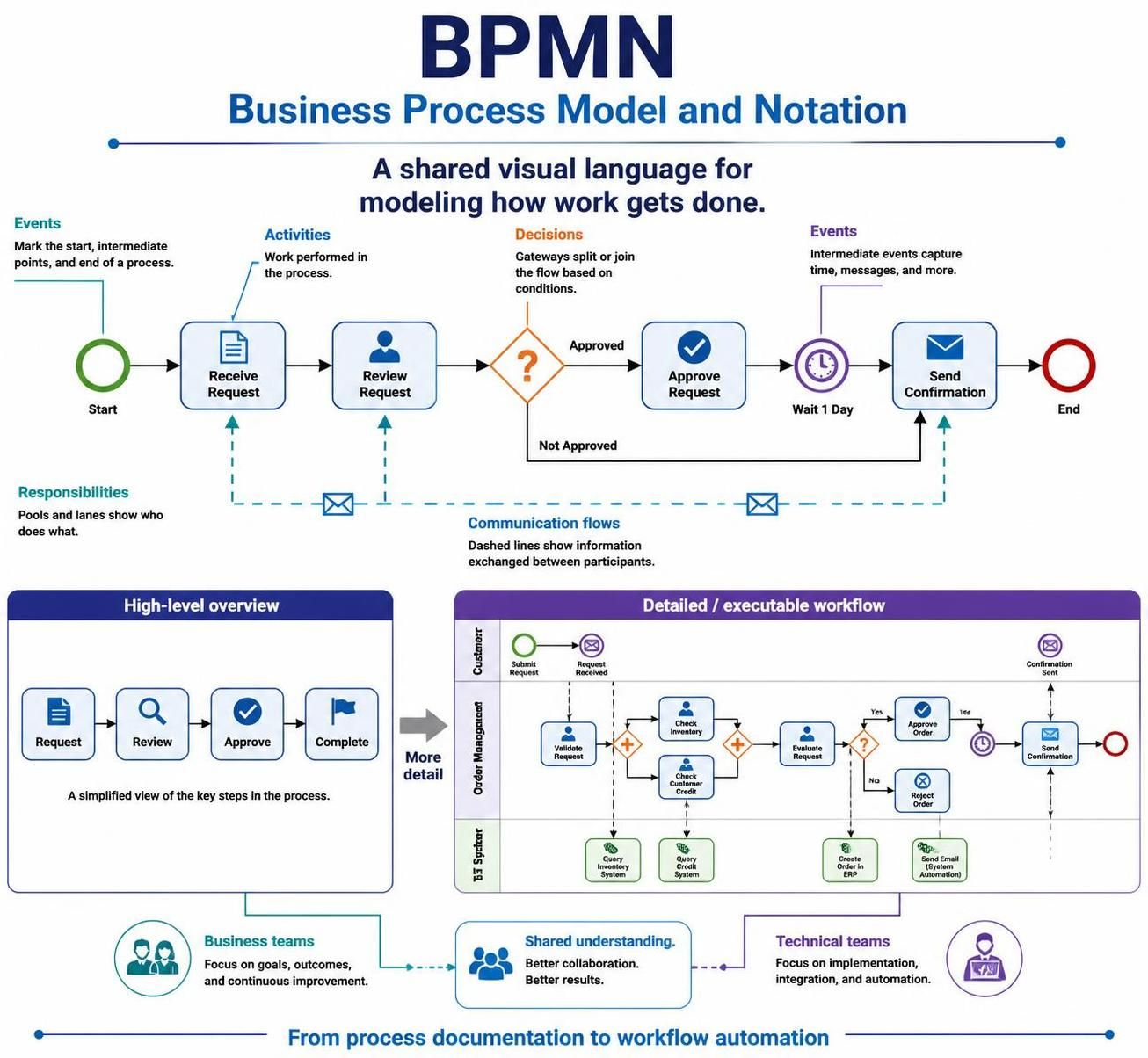
Business Process Model and Notation, commonly called BPMN, is a standardized visual language for describing how business processes work. It helps people represent activities, decisions, events, responsibilities, and communication flows in a way that both business and technical teams can understand.
BPMN diagrams can be as simple as a high-level overview of a process or as detailed as an executable workflow used by process-management software.
1. What Is BPMN?
BPMN is a graphical notation for modeling business processes. A BPMN diagram shows:
-
What activities take place
-
In what order they occur
-
Which events start, interrupt, or end a process
-
Where decisions are made
-
Who performs each activity
-
How different participants communicate
-
What happens when exceptions occur
For example, an online order process might include:
-
Customer places an order.
-
The system checks inventory.
-
The payment is authorized.
-
The order is packed.
-
The order is shipped.
-
The customer receives confirmation.
BPMN can represent this process visually using events, activities, gateways, pools, lanes, and connecting flows.
2. Why Use BPMN?
BPMN is useful because it creates a common language for people with different backgrounds.
A business analyst may use BPMN to document current processes. A process owner may use it to identify inefficiencies. A software developer may use it to design workflow automation. Managers may use it to understand responsibilities and bottlenecks.
The main benefits include:
-
Clarity: Processes are easier to understand than when described only in text.
-
Standardization: BPMN uses internationally recognized symbols and rules.
-
Communication: Business and technical teams can discuss the same model.
-
Process improvement: Unnecessary steps, delays, and duplicated work become visible.
-
Documentation: Diagrams provide a durable record of how work is performed.
-
Automation support: Detailed BPMN models can be implemented in workflow systems.
-
Exception analysis: Errors, cancellations, timeouts, and alternative paths can be modeled explicitly.
3. BPMN at Different Levels of Detail
BPMN diagrams can be created at several levels.
High-level process map
A high-level diagram shows only the major stages of a process.
Example:
Receive Order → Process Payment → Prepare Shipment → Deliver Order
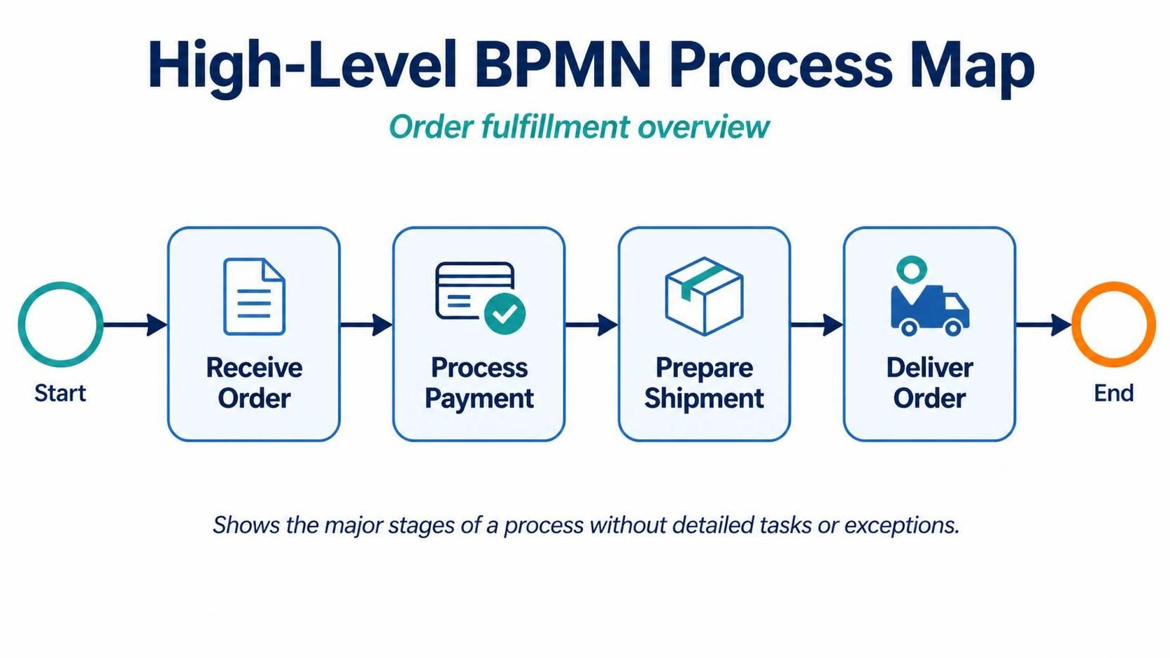
This is useful for presentations and initial discussions.
Detailed process model
A detailed model shows individual tasks, decision points, exceptions, participants, and message exchanges.
Example:
Order Received
      ↓
Check Inventory
      ↓
Is Item Available?
   ↙          ↘
 No            Yes
 ↓              ↓
Notify         Authorize Payment
Customer             ↓
                  Payment Approved?
                    ↙       ↘
                  No         Yes
                  ↓           ↓
              Cancel Order  Pack Order
                                  ↓
                             Ship Order
Executable process model
An executable model contains enough detail for workflow software or a business process management system to run the process. It may include technical service tasks, timers, data mappings, and formal exception handling.
A useful rule is:
Start with the simplest model that answers the current question. Add detail only when it is needed.
4. Core BPMN Elements
The most important BPMN elements are:
-
Flow objects
-
Events
-
Activities
-
Gateways
-
-
Connecting objects
-
Sequence flows
-
Message flows
-
Associations
-
-
Swimlanes
-
Pools
-
Lanes
-
-
Artifacts
-
Data objects
-
Groups
-
Text annotations
-
These elements work together to describe the behavior and organization of a process.
5. Events
An event represents something that happens during a process. Events can start a process, occur while it is running, or mark its completion.
Events are generally drawn as circles.
Start events
A start event indicates where a process begins.
It may be triggered by:
-
A customer submitting a request
-
A message arriving
-
A scheduled time
-
A signal from another process
-
A condition becoming true
-
A rule or business event
A basic start event is usually shown as a circle with a thin border.
Example:
○ Start → Review Request
A start event answers the question:
What causes this process to begin?
Intermediate events
An intermediate event occurs between the start and end of a process. It can represent something that happens during the process or something that the process must wait for.
Examples include:
-
Waiting for a customer response
-
Receiving a message
-
Waiting for a timer
-
Catching an error
-
Sending a notification
-
Escalating an issue
Intermediate events are usually shown as circles with a double border.
Example:
Review Request → ◉ Wait for Approval → Complete Request
End events
An end event indicates that a process path has finished.
Possible outcomes include:
-
Successful completion
-
Cancellation
-
Error
-
Compensation
-
Termination
-
A message being sent
An end event is generally represented by a circle with a thick border.
Example:
Complete Shipment → ◎ Order Fulfilled
Common event types
Message event
Represents the sending or receiving of a message.
Examples:
-
Receive a customer application
-
Send an approval notification
-
Receive confirmation from a supplier
Timer event
Represents a date, time, duration, or recurring schedule.
Examples:
-
Wait two business days
-
Start every Monday
-
Escalate if no response is received within 24 hours
Error event
Represents an error that interrupts or redirects the process.
Examples:
-
Payment service unavailable
-
Required document missing
-
Data validation failure
Conditional event
Occurs when a specified condition becomes true.
Example:
Wait until account balance is below the threshold
Escalation event
Represents a business escalation that does not necessarily mean the process has technically failed.
Example:
-
Escalate a delayed case to a supervisor
-
Notify management when a priority customer complains
Compensation event
Represents an action that reverses or compensates for a previous activity.
Example:
-
Refund a payment after canceling an order
-
Reverse a reservation after a transaction fails
Signal event
Represents a broadcast communication that may be received by multiple processes.
Example:
-
Broadcast a system maintenance notification
6. Activities
An activity represents work performed within a process. Activities are drawn as rounded rectangles.
Activities include:
-
Entering information
-
Reviewing a document
-
Approving a request
-
Sending an invoice
-
Calling a customer
-
Running a system check
Tasks
A task is a single unit of work that is not broken down further in the current diagram.
Examples:
-
Verify Customer Identity
-
Create Invoice
-
Approve Refund
-
Send Confirmation Email
A task is commonly represented as:
╭────────────────────╮
│  Verify Identity   │
╰────────────────────╯
Sub-processes
A sub-process is an activity that contains its own internal process details.
It is useful when a process step is complex or reusable.
Example:
Order Fulfillment
The high-level diagram may show only the sub-process. A separate diagram can describe its internal steps:
Pick Items → Pack Items → Print Label → Dispatch Package
A sub-process is typically indicated by a small plus symbol inside the activity.
Use a sub-process when:
-
The activity contains several steps
-
The details are not necessary at the current level
-
The same group of steps is reused
-
You want to keep the main diagram readable
Call activities
A call activity invokes a reusable process or global activity.
For example, several processes may call the same:
Perform Credit Check
This avoids duplicating the same detailed logic in multiple diagrams.
Types of tasks
BPMN can distinguish tasks by their behavior.
User task
Work performed by a person using a software application.
Examples:
-
Review loan application
-
Approve expense report
-
Enter customer information
Manual task
Work performed by a person without relying on a process application.
Examples:
-
Inspect physical equipment
-
Deliver a signed document
-
Package a product manually
Service task
Work performed automatically by a system or service.
Examples:
-
Calculate tax
-
Query a database
-
Send an automated email
-
Call a payment service
Script task
Work performed by an internal script or program.
Example:
-
Transform incoming data
-
Calculate a score
-
Generate a formatted document
Business rule task
Uses business rules to determine an outcome.
Examples:
-
Determine customer eligibility
-
Calculate a discount
-
Set a risk category
Send task
Sends a message to another participant.
Examples:
-
Send purchase order to supplier
-
Send approval notice to customer
Receive task
Waits for a message to arrive.
Examples:
-
Receive signed contract
-
Receive shipping confirmation
7. Gateways
A gateway controls how the process splits, joins, or routes sequence flows. Gateways are normally drawn as diamonds.
Gateways answer questions such as:
-
Which path should the process follow?
-
Can several paths happen at the same time?
-
Should the process wait for all branches?
-
Should the process continue after one branch finishes?
Exclusive gateway
An exclusive gateway, also called an XOR gateway, selects exactly one path based on a condition.
Example:
Check Payment
      ↓
  ◇ Payment Approved?
    ↙          ↘
  Yes           No
  ↓             ↓
Ship Order   Reject Order
Only one outgoing path is followed.
Typical conditions include:
-
Amount is greater than a threshold
-
Customer is eligible
-
Document is complete
-
Payment was approved
Inclusive gateway
An inclusive gateway, or OR gateway, activates one or more paths depending on conditions.
Example:
◇ Which notifications are required?
   ├── Send Email
   ├── Send SMS
   └── Notify Account Manager
One, two, or all three paths may be selected.
Use an inclusive gateway when multiple conditions can be true at the same time.
Parallel gateway
A parallel gateway, or AND gateway, starts multiple paths simultaneously.
Example:
          ┌── Check Inventory ──┐
Order ────◇                      ◇── Continue
          └── Check Credit ─────┘
The first gateway creates parallel work. The second gateway synchronizes the branches and normally waits for all of them to finish.
Event-based gateway
An event-based gateway routes the process based on whichever event happens first.
Example:
Wait for Customer Response
      ◇
     ↙ ↘
Response received   Timer expires
     ↓                   ↓
Continue review      Escalate case
This is useful when the process waits for alternatives such as:
-
A message or a timeout
-
Approval or rejection
-
Payment or cancellation
-
A response or an escalation deadline
Complex gateway
A complex gateway represents advanced routing behavior that cannot be expressed easily with the standard gateway types.
It should be used sparingly because it may be harder for readers and workflow systems to interpret.
8. Sequence Flows
A sequence flow shows the order in which activities, events, and gateways occur within a process.
It is drawn as a solid line with a filled arrowhead.
Start → Register Customer → Verify Details → End
Sequence flows can include conditions.
Example:
◇ Is the application complete?
  ├── Yes → Approve Application
  └── No  → Request More Information
Default flow
A default flow is followed when no other outgoing condition is satisfied. It is useful as a fallback path.
For example:
If score ≥ 80 → Auto-approve
If score < 80  → Manual review
Otherwise     → Escalate
The escalation path could be marked as the default.
Sequence flow limitations
Sequence flows should generally remain within a single pool. They are not normally used to connect separate participants. Communication between separate pools should be modeled with message flows.
9. Message Flows
A message flow shows communication between separate participants.
It is drawn as a dashed line with an open arrowhead.
Example:
Customer Pool - - - - → Company Pool
Message flows can represent:
-
A submitted application
-
An invoice
-
A confirmation email
-
A purchase order
-
A request for information
-
A shipping notification
A message flow indicates communication, not process order. It does not mean that one participant’s activity directly controls the other participant’s sequence.
10. Pools and Lanes
Pools and lanes organize responsibilities.
Pools
A pool represents a participant in a process. A participant may be:
-
A company
-
A customer
-
A supplier
-
A department
-
An external system
-
A government agency
-
Another independent process
Example:
┌──────────────────────────────────────────────┐
│ Customer                                     │
│                                              │
│ Place Order ──────── Receive Confirmation    │
└──────────────────────────────────────────────┘

┌──────────────────────────────────────────────┐
│ Online Store                                 │
│                                              │
│ Receive Order ───── Process Payment          │
└──────────────────────────────────────────────┘
Each pool may contain its own process flow. Communication between pools is shown with message flows.
Lanes
A lane is a subdivision within a pool. It usually represents a role, department, team, or system.
Example:
┌─────────────────────────────────────────────┐
│ Sales       │ Receive Request                │
├─────────────────────────────────────────────┤
│ Finance     │ Verify Payment                 │
├─────────────────────────────────────────────┤
│ Warehouse   │ Pick and Pack Order            │
├─────────────────────────────────────────────┤
│ Shipping    │ Dispatch Package               │
└─────────────────────────────────────────────┘
Lanes help answer:
Who is responsible for each activity?
Possible lane divisions include:
-
By department
-
By job role
-
By location
-
By system
-
By customer type
-
By stage of the process
Pool versus lane
The distinction is important:
-
A pool represents an independent participant.
-
A lane represents a responsibility area within a participant.
For example, a customer and a retailer would normally be separate pools. Sales, Finance, and Warehouse within the retailer might be represented as lanes.
11. Data Objects and Artifacts
Artifacts provide additional information without directly controlling the process flow.
Data objects
A data object represents information used or produced by an activity.
Examples:
-
Customer application
-
Purchase order
-
Invoice
-
Contract
-
Shipping label
-
Approval record
Example:
Receive Application → Review Application
                           │
                           └── [Customer Application]
A data object may be:
-
An input to an activity
-
An output from an activity
-
Updated during the process
-
Passed from one activity to another
Data stores
A data store represents information that persists beyond the immediate process instance.
Examples:
-
Customer database
-
Document repository
-
Inventory system
-
Employee records
A data store may be connected to tasks that read or update it.
Text annotations
A text annotation adds explanatory information to a diagram.
Examples:
-
“Requests above $10,000 require director approval.”
-
“This task is completed automatically.”
-
“The customer has five business days to respond.”
Annotations clarify a model but do not change its behavior.
Groups
A group visually surrounds related elements. It is used for documentation and organization, not for controlling the process.
A group might identify:
-
Activities handled by a particular team
-
Steps belonging to a regulatory requirement
-
A phase of a project
-
A set of activities being analyzed
12. A Simple BPMN Example
Consider a customer complaint process.
Start: Complaint Received
          ↓
Register Complaint
          ↓
Classify Complaint
          ↓
      ◇ Is it urgent?
       ↙          ↘
     Yes           No
      ↓             ↓
Assign Manager   Assign Support Agent
       ↘         ↙
        Investigate Complaint
                  ↓
          Prepare Response
                  ↓
          Send Response
                  ↓
          ◇ Customer Satisfied?
             ↙          ↘
           Yes           No
            ↓             ↓
        Close Case   Escalate Case
            ↓             ↓
              End / Further Review
This example contains:
-
A start event
-
Several tasks
-
An exclusive gateway
-
Merging paths
-
A second decision
-
Different outcomes
A detailed BPMN model could additionally show:
-
The customer as a separate pool
-
Message flows for the complaint and response
-
A timer for response deadlines
-
A user task for manual investigation
-
An escalation event
-
A data object representing the complaint record
13. How to Create a BPMN Diagram
Step 1: Define the process scope
Decide where the process begins and ends.
For example:
-
Start: Customer submits a complaint
-
End: Complaint is closed or escalated
Avoid trying to model the entire organization at once.
Step 2: Identify the participants
List the people, departments, systems, and external organizations involved.
Example:
-
Customer
-
Customer Service
-
Support Team
-
Manager
-
Case Management System
Use pools for independent participants and lanes for internal roles or departments.
Step 3: List the main activities
Write down the major tasks in the order they normally occur.
Example:
-
Receive complaint
-
Register complaint
-
Classify complaint
-
Assign owner
-
Investigate complaint
-
Prepare response
-
Send response
-
Close case
At this stage, focus on the work rather than the symbols.
Step 4: Identify start and end events
Ask:
-
What triggers the process?
-
What outcomes can finish it?
-
Are there multiple end conditions?
A process may have more than one end event, such as:
-
Order completed
-
Order canceled
-
Order rejected
Step 5: Add decisions
Look for questions that change the process path.
Examples:
-
Is the request complete?
-
Is the customer eligible?
-
Is the payment approved?
-
Is the issue urgent?
Choose the gateway type carefully:
-
Exclusive: exactly one path
-
Inclusive: one or more paths
-
Parallel: all paths
-
Event-based: whichever event happens first
Step 6: Add exceptions
Normal flows are only part of a real process. Include situations such as:
-
Missing information
-
Rejected payments
-
Customer cancellation
-
System failure
-
Expired deadlines
-
Unavailable employees
-
Escalations
Exceptions can be modeled with gateways, boundary events, intermediate events, or alternative end events.
Step 7: Assign responsibilities
Place tasks in the appropriate lanes or pools.
This makes unclear ownership visible. If no person, team, or system can be assigned to a task, the task may need clarification.
Step 8: Add messages and data
Show important communication and information.
Examples:
-
Customer sends an application
-
Finance sends an approval
-
Warehouse receives a packing request
-
A system updates the order database
Do not add every document or system detail unless it helps explain the process.
Step 9: Validate the diagram
Check that:
-
There is a clear start event
-
Every path has a logical continuation
-
Tasks use meaningful names
-
Gateways have understandable conditions
-
Parallel branches are properly joined
-
Message flows connect appropriate pools
-
Responsibilities are clear
-
End events represent genuine outcomes
-
The diagram can be understood without a lengthy verbal explanation
14. Naming BPMN Elements
Good names make diagrams much easier to read.
Name tasks with a verb and an object
Good examples:
-
Review Application
-
Approve Request
-
Send Invoice
-
Update Customer Record
-
Validate Payment
Avoid vague names such as:
-
Processing
-
Handling
-
Action
-
Step 1
-
Manage
Name gateways as questions
Good examples:
-
Is Payment Approved?
-
Is the Application Complete?
-
Does the Customer Qualify?
-
Is the Item in Stock?
The outgoing sequence flows can then be labeled:
-
Yes
-
No
-
Approved
-
Rejected
-
Available
-
Unavailable
Name events as things that happen
Good examples:
-
Order Received
-
Payment Confirmed
-
Approval Deadline Reached
-
Shipment Delivered
Avoid using task-style names for events, such as “Check Order,” unless the event genuinely represents an action.
15. Common BPMN Modeling Patterns
Approval pattern
Submit Request → Review Request → ◇ Approved?
                                  ↙       ↘
                               Yes         No
                                ↓           ↓
                          Fulfill Request  Reject Request
Rework pattern
Create Document → Review Document → ◇ Correct?
                                      ↙      ↘
                                    Yes        No
                                     ↓          ↓
                                  Submit   Revise Document
                                                ↺
The loop returns to the revision or review step.
Parallel work pattern
Start → ◇
       ├── Perform Check A ──┐
       └── Perform Check B ──┴── ◇ → Continue
The joining gateway waits for both checks.
Timeout pattern
Send Request → Wait for Response
                    ◇
                   ↙ ↘
            Response     Timer expires
               ↓              ↓
           Continue        Escalate
Cancellation pattern
Process Order
      │
      └── Boundary Cancel Event → Cancel Order
A boundary event is attached to the edge of an activity and can interrupt or redirect it when a particular event occurs.
16. Boundary Events
A boundary event is attached to the boundary of an activity. It reacts to something that happens while that activity is in progress.
Examples:
-
A timer expires while waiting for approval
-
An error occurs during payment
-
A customer cancels an order
-
A message arrives while a case is being reviewed
Boundary events may be:
-
Interrupting: The original activity stops.
-
Non-interrupting: The original activity continues while another path starts.
Example:
┌───────────────────────┐
│ Wait for Approval     │
└──────────○────────────┘
           ↓
      Escalate Request
If the boundary timer is interrupting, the waiting task ends when the timer fires. If it is non-interrupting, the escalation may begin while the original task remains active.
17. Collaboration Diagrams
A collaboration diagram shows interactions between multiple participants.
Example participants might include:
-
Customer
-
Retailer
-
Payment Provider
-
Shipping Company
Each participant may have its own pool. Message flows show communication between them.
Customer                  Retailer              Payment Provider
   │                         │                         │
   │── Order ───────────────>│                         │
   │                         │── Payment Request ────>│
   │                         │<── Payment Result ─────│
   │<── Confirmation ────────│                         │
Collaboration diagrams are especially useful for:
-
Customer journeys
-
Supplier interactions
-
Interdepartmental processes
-
System integrations
-
Service-oriented workflows
18. Choreography Diagrams
A choreography focuses on the messages exchanged between participants rather than the internal work of each participant.
For example:
Customer submits order
Retailer requests payment
Payment provider confirms payment
Retailer sends shipping notice
Choreography diagrams are useful when the main concern is interaction between participants.
They are less focused on:
-
Internal employee tasks
-
Departmental responsibilities
-
Detailed exception handling
-
Internal system operations
19. Orchestration versus Collaboration
These concepts describe different perspectives.
Orchestration focuses on the internal sequence of activities controlled by one participant, such as a retailer’s order process.
Collaboration focuses on how multiple participants interact through messages, such as the retailer communicating with a customer and payment provider.
A complete solution may use both:
-
An internal process diagram for each organization
-
A collaboration diagram showing communication between them
20. BPMN Modeling Best Practices
Keep diagrams readable
Avoid placing too many elements in one diagram. If a process becomes difficult to follow, divide it into subprocesses or separate diagrams.
Use a consistent direction
Most diagrams flow from left to right or from top to bottom. Choose one direction and use it consistently.
Avoid crossing lines
Crossing sequence flows make diagrams difficult to understand. Rearrange elements or use subprocesses to reduce visual clutter.
Use gateways purposefully
Do not insert gateways merely because a path changes direction. A gateway should represent a meaningful decision, merge, split, or synchronization point.
Label conditions clearly
Instead of unlabeled arrows, use conditions such as:
-
Approved
-
Rejected
-
Complete
-
Incomplete
-
In stock
-
Out of stock
Separate normal flow from exceptions
The main path should be easy to identify. Error, timeout, cancellation, and escalation paths should be modeled clearly without overwhelming the normal flow.
Model responsibility explicitly
Every meaningful task should have a responsible role, department, participant, or system.
Avoid excessive technical detail
A business-level model does not need every database query, screen field, or software function. Add technical detail only when the diagram is intended for implementation or automation.
Avoid excessive ambiguity
A good model should make clear:
-
What starts the process
-
What each task accomplishes
-
Who performs each task
-
What each decision means
-
What happens in each outcome
-
How the process ends
21. Common BPMN Mistakes
Treating every participant as a lane
A customer and a company are normally separate participants and should usually be modeled as separate pools, not lanes in one pool.
Using sequence flows between pools
Sequence flows represent internal process order. Use message flows for communication between separate pools.
Leaving gateway conditions unclear
A diamond without clear conditions can make it impossible to understand why one path is selected over another.
Forgetting to join parallel paths
When a parallel gateway splits a process, the branches often need a corresponding join gateway. Otherwise, the process may continue before all required work is complete.
Modeling tasks as events
“Review Application” is a task because work is performed. “Application Received” is an event because something happened.
Using too many symbols
A diagram full of specialized events and gateways may be technically detailed but difficult to understand. Use the simplest suitable element.
Omitting exception paths
Processes rarely succeed every time. Model meaningful errors, delays, cancellations, and rework loops.
Mixing different levels of detail
A diagram should not show a broad activity such as “Fulfill Order” beside extremely detailed steps such as “Open Warehouse Screen” and “Click Print Label” unless the difference is intentional.
22. BPMN and Other Process Diagrams
BPMN is not the only way to represent processes.
| Diagram type | Main purpose |
|---|---|
| BPMN | Detailed business process behavior, responsibilities, events, and communication |
| Flowchart | General step-by-step logic |
| UML activity diagram | Software and system activity modeling |
| Value stream map | Process time, delays, and value delivery |
| SIPOC diagram | Suppliers, inputs, process, outputs, and customers |
| Customer journey map | Customer experience across stages |
| Data flow diagram | Movement and transformation of data |
BPMN is particularly strong when a process includes multiple participants, decisions, events, messages, and exceptions.
23. BPMN Tools
BPMN diagrams can be created with:
-
Dedicated BPMN modeling applications
-
Business process management platforms
-
Diagramming tools with BPMN symbol libraries
-
Workflow automation systems
-
Collaborative whiteboarding tools
When selecting a tool, consider:
-
BPMN standard support
-
Collaboration features
-
Version history
-
Validation capabilities
-
Export formats
-
Workflow execution support
-
Integration with existing systems
-
Support for subprocesses and reusable models
24. A Practical Modeling Checklist
Before finalizing a BPMN diagram, ask:
Scope
-
Is the start point clear?
-
Is the end point clear?
-
Is the diagram focused on one process?
Flow
-
Does every sequence flow have a logical purpose?
-
Are all paths connected correctly?
-
Are loops and parallel branches clear?
Decisions
-
Is each gateway necessary?
-
Are gateway conditions labeled?
-
Is the correct gateway type being used?
Responsibilities
-
Is every task assigned to a role, department, system, or participant?
-
Are external participants separated into pools?
Events
-
Are important timers, messages, errors, cancellations, and escalations represented?
-
Are end events meaningful?
Readability
-
Can a new reader follow the process?
-
Are labels concise and consistent?
-
Are there unnecessary symbols or crossing lines?
Completeness
-
Are important exceptions included?
-
Are relevant documents and data stores shown?
-
Does the model match the actual process?
25. Summary
BPMN provides a structured way to describe business processes visually. Its most important concepts are:
-
Events show what happens.
-
Activities show work being performed.
-
Gateways control decisions, parallel work, and synchronization.
-
Sequence flows show the order of activities within a process.
-
Message flows show communication between participants.
-
Pools represent independent participants.
-
Lanes divide responsibility within a participant.
-
Data objects and artifacts provide supporting information.
-
Sub-processes organize complex or reusable process logic.
A strong BPMN diagram is clear, purposeful, and appropriately detailed. Begin with the process goal and scope, identify the participants and activities, add decisions and exceptions, assign responsibilities, and validate the result with the people who perform the work.